Mitsubishi Mini Split Installation Manual: A Comprehensive Guide
This manual details the Marrs standard for installing a Bellingham Mitsubishi Ductless Mini Split. It covers everything from initial planning to final testing‚ ensuring a complete and efficient cooling/heating system.
Always refer to the complete installation manual and operating instructions for safety and proper operation. Selecting the correct installation location is crucial‚ and caution must be observed throughout the process.
Model-specific details are found in section 1-3‚ while multi-unit installations require referencing the dedicated multi-unit installation manual. Prioritize safety by adhering to all outlined precautions.
Understanding Mini Split Systems
Mitsubishi mini-split systems represent a versatile and efficient heating and cooling solution‚ diverging from traditional ducted systems. These systems utilize a split design‚ comprising an indoor unit and an outdoor unit connected by refrigerant lines and electrical wiring. This configuration allows for zoned temperature control‚ enabling independent heating or cooling of individual rooms or areas within a building.
Unlike central air systems that rely on ductwork‚ mini-splits offer ductless operation‚ minimizing energy loss associated with leaky or poorly insulated ducts. This results in improved energy efficiency and potentially lower utility bills. The indoor unit‚ often mounted on a wall or ceiling‚ quietly distributes conditioned air directly into the space. The outdoor unit houses the compressor and condenser‚ responsible for heat exchange.
Installation requires careful planning‚ considering factors like room size‚ insulation‚ and climate. Proper refrigerant line sizing and electrical connections are critical for optimal performance and longevity. Understanding the system’s components and operational principles is fundamental before attempting any installation or maintenance procedures. These systems are ideal for additions‚ renovations‚ or spaces where ductwork is impractical or cost-prohibitive.
Mitsubishi’s commitment to innovation has positioned them as a leader in mini-split technology‚ offering a wide range of models with advanced features like inverter technology and smart home integration.
Components of a Mitsubishi Mini Split
A Mitsubishi mini-split system consists of several key components working in harmony to deliver efficient heating and cooling. The indoor unit‚ available in various styles (wall-mounted‚ ceiling cassette‚ floor-standing)‚ contains the evaporator coil and fan‚ responsible for distributing conditioned air into the room.
The outdoor unit houses the compressor‚ condenser coil‚ and fan‚ which expel heat during cooling and absorb heat during heating. Refrigerant lines – typically copper tubing – connect the indoor and outdoor units‚ circulating the refrigerant that transfers heat. These lines require careful insulation to prevent energy loss.
A split box‚ often mounted on the wall‚ serves as a junction point for refrigerant lines‚ condensate drain‚ and electrical connections. The remote control allows users to adjust temperature‚ fan speed‚ and other settings. Electrical wiring provides power to both indoor and outdoor units‚ requiring adherence to local electrical codes.
Additional components may include a condensate pump (for situations where gravity drainage isn’t possible)‚ mounting brackets‚ and various connectors. Understanding the function of each component is crucial for successful installation and troubleshooting. Refer to the installation manual for detailed diagrams and specifications.
Safety Precautions Before Installation
Prior to commencing any installation work‚ a thorough review of the installation manual and operating instructions is paramount. Always disconnect electrical power to the intended installation area to prevent electric shock. Working with refrigerant requires specialized knowledge and adherence to EPA regulations; improper handling can be hazardous.

Wear appropriate personal protective equipment (PPE)‚ including safety glasses‚ gloves‚ and potentially a respirator‚ especially when handling refrigerant lines or working in confined spaces. Ensure the installation location can support the weight of both the indoor and outdoor units‚ utilizing appropriate mounting hardware.
Be mindful of potential hazards such as sharp edges on sheet metal components and the risk of falling from ladders or roofs. Never attempt to modify or repair any component of the mini-split system without proper training and authorization. Observe all local building codes and electrical regulations.
The manual emphasizes the importance of safety‚ stating “The following should always be observed for safety.” Improper installation can lead to system malfunction‚ property damage‚ or personal injury. If unsure about any aspect of the installation‚ consult a qualified HVAC technician.
Required Tools and Materials
Successful Mitsubishi mini-split installation necessitates a comprehensive toolkit. Essential tools include a refrigerant recovery machine‚ vacuum pump‚ manifold gauge set‚ flaring tool‚ tube cutter‚ and a reliable set of wrenches – both open-end and adjustable. Electrical tools such as wire strippers‚ a multimeter‚ and appropriate screwdrivers are also crucial.
Beyond tools‚ a specific list of materials is required. This encompasses refrigerant piping (copper tubing)‚ insulation for the refrigerant lines‚ electrical wiring (sized appropriately for the unit)‚ conduit for wiring protection‚ and mounting brackets for both the indoor and outdoor units.
Additional materials include brazing alloy‚ nitrogen gas for pressure testing‚ sealant for pipe connections‚ and appropriate fasteners (screws‚ bolts‚ anchors) for secure mounting. The installation manual explicitly lists “Required Tools”‚ emphasizing the need to follow these guidelines meticulously.
Ensure all materials meet relevant industry standards and are compatible with the specific Mitsubishi mini-split model being installed. Having a well-stocked inventory beforehand streamlines the installation process and minimizes delays. Refer to the manual for model-specific material requirements.
Step 1: Planning the Installation Location
Careful planning is paramount before commencing any installation. Begin by assessing the cooling and heating needs of the space‚ determining the appropriate BTU capacity for the Mitsubishi mini-split unit. Consider factors like room size‚ insulation levels‚ sun exposure‚ and the number of occupants.
Indoor unit placement significantly impacts performance. Avoid direct sunlight‚ heat sources‚ and areas with obstructions that could impede airflow. Ensure sufficient space around the unit for maintenance and proper ventilation. The manual cautions about selecting the installation location‚ emphasizing its importance.

Outdoor unit location requires similar consideration. Choose a level‚ stable surface that can support the unit’s weight. Allow adequate clearance around the unit for airflow and service access. Avoid locations prone to excessive snow accumulation or debris buildup.
Plan the routing of refrigerant lines and electrical wiring‚ minimizing bends and ensuring compliance with local codes. Consider the distance between the indoor and outdoor units‚ as this affects refrigerant charge and system efficiency. A thorough site survey is essential for optimal placement.

Step 2: Mounting the Indoor Unit
Securely mounting the indoor unit is crucial for stable operation and preventing vibrations. Begin by marking the mounting bracket locations on the wall‚ ensuring they align with pre-drilled holes in the unit. Use appropriate wall anchors to support the bracket’s weight‚ especially on drywall or plaster surfaces.
The bracket for the split box is mounted to the wall using suitable fasteners. Double-check the bracket’s levelness before proceeding. Carefully lift the indoor unit onto the mounted bracket‚ ensuring it’s firmly seated and locked into place.
Connect the drain hose to the designated outlet‚ ensuring a proper slope for condensate drainage. Improper drainage can lead to water damage and system malfunction. Verify that the drain hose is securely connected and free from kinks or obstructions.
Before proceeding‚ inspect the mounting for stability. A wobbly or insecure unit can cause noise and potential damage. Ensure all screws are tightened and the unit is firmly attached to the wall. This step is vital for long-term reliability.
Step 3: Installing the Outdoor Unit
Selecting a suitable location for the outdoor unit is paramount. Ensure adequate ventilation‚ avoiding obstructions like shrubs or walls that could restrict airflow. The unit should be placed on a level surface‚ ideally a concrete pad‚ to minimize vibration and noise.
Maintain sufficient clearance around the unit for service access and proper operation. Refer to the installation manual for specific clearance requirements. Secure the unit to the pad using appropriate bolts and anchors‚ protecting it from wind and potential theft.
Carefully consider the proximity to electrical connections and refrigerant lines. Minimize the length of these runs to optimize efficiency and reduce potential issues. Ensure the outdoor unit is protected from direct sunlight and harsh weather conditions whenever possible.
Before finalizing the installation‚ double-check all connections and ensure the unit is stable and securely mounted. A properly installed outdoor unit is essential for the overall performance and longevity of the mini-split system.
Step 4: Refrigerant Line Installation
Proper refrigerant line installation is critical for system performance and preventing leaks. Carefully uncoil the refrigerant lines‚ avoiding kinks or sharp bends that could restrict flow. Ensure the lines are the correct size and length as specified in the installation manual.
When routing the lines‚ protect them from physical damage and exposure to direct sunlight. Use pipe supports to secure the lines along their run‚ preventing strain on the connections. Maintain a slight slope downwards from the indoor to the outdoor unit to facilitate oil return.
Before connecting the lines‚ ensure the flare nuts are properly tightened and the connections are clean and free of debris. Use a torque wrench to tighten the nuts to the manufacturer’s specified torque. Avoid over-tightening‚ which can damage the fittings.
After making all connections‚ carefully inspect for any signs of leaks. A properly installed refrigerant line set is essential for efficient operation and preventing environmental damage. Refer to the manual for detailed diagrams and instructions;
Step 5: Electrical Connections – Indoor Unit
Before commencing electrical work‚ disconnect the main power supply to prevent electrical shock. Identify the correct wiring diagram for your specific indoor unit model within the installation manual. Ensure the wire gauge is appropriate for the circuit breaker size and the unit’s power requirements.
Connect the power supply wires to the designated terminals on the indoor unit’s control board‚ carefully matching the live‚ neutral‚ and ground wires. Securely tighten all screw terminals to prevent loose connections and potential hazards. Double-check all connections against the wiring diagram.
If using a field-supplied disconnect switch‚ wire it according to local electrical codes and the manufacturer’s instructions. Ensure the disconnect switch is readily accessible for maintenance and emergencies. Proper grounding is crucial for safety and system performance.

After completing the wiring‚ carefully inspect all connections and ensure no bare wires are exposed. Restore power and verify the indoor unit responds correctly. Refer to the manual for troubleshooting electrical issues.
Step 6: Electrical Connections – Outdoor Unit
Prioritize safety by disconnecting the main power supply before initiating any electrical connections to the outdoor unit. Consult the installation manual for the specific wiring diagram corresponding to your model. Verify the correct voltage and amperage requirements before proceeding.
Connect the power supply wires to the designated terminals within the outdoor unit’s electrical compartment‚ meticulously matching live‚ neutral‚ and ground wires. Securely tighten all terminal screws to prevent loosening and potential electrical hazards. Double-check all connections against the provided diagram.
If a field-supplied disconnect switch is utilized‚ ensure it’s wired in accordance with local electrical codes and the manufacturer’s guidelines. The disconnect switch must be easily accessible for maintenance and emergency shut-off. Proper grounding is paramount for safety and optimal system operation.
Following wiring completion‚ thoroughly inspect all connections‚ confirming no bare wires are exposed. Restore power and verify the outdoor unit functions as expected. Consult the manual for troubleshooting any electrical issues encountered.
Step 7: Vacuuming the Refrigerant Lines
Properly vacuuming the refrigerant lines is critical to remove air and moisture‚ ensuring optimal system performance and preventing compressor damage. Connect a vacuum pump with a manifold gauge set to the service ports on both the indoor and outdoor units. Ensure all connections are tight to maintain a vacuum seal;
Initiate the vacuum pump and allow it to run for a minimum of 30-60 minutes‚ or as specified in the installation manual. This extended period ensures complete evacuation of non-condensables. Monitor the vacuum gauge; it should reach and maintain a deep vacuum‚ typically below 500 microns.

During the vacuuming process‚ periodically check all refrigerant line connections for leaks using a leak detector. Any detected leaks must be addressed and resealed before continuing. A thorough vacuum is essential for a long-lasting and efficient mini-split system.
Once the desired vacuum level is achieved‚ close the manifold gauge set valves and isolate the system. Carefully observe the vacuum gauge for any signs of vacuum loss‚ indicating a potential leak. Proceed to the refrigerant charging stage only after confirming a stable vacuum.
Step 8: Charging the Refrigerant
Refrigerant charging must be performed by a qualified technician‚ adhering strictly to the manufacturer’s specifications outlined in the installation manual. Incorrect refrigerant charge levels can significantly impact system efficiency and potentially damage the compressor.
Connect the refrigerant manifold gauge set to the service ports‚ ensuring proper connections for high and low sides. Slowly introduce the specified type and amount of refrigerant into the system‚ typically using a weighing scale for accurate measurement. Refer to the unit’s nameplate for the correct refrigerant type and charge weight.
Monitor the system pressures during charging‚ comparing them to the target pressures specified in the manual. Adjust the refrigerant flow rate as needed to achieve the desired pressures. Avoid overcharging or undercharging the system‚ as both can lead to performance issues.
After completing the charging process‚ carefully check all refrigerant line connections for leaks using a leak detector. Document the refrigerant charge weight and pressures for future reference. A precise refrigerant charge is vital for optimal system operation and longevity.
Step 9: Performing a Test Run
Following refrigerant charging‚ a comprehensive test run is crucial to verify proper system operation. Power up both the indoor and outdoor units‚ and activate the system using the remote control. Observe the system’s response to various settings – cooling‚ heating‚ fan-only‚ and auto modes.
Monitor the airflow from the indoor unit‚ ensuring it’s consistent and unobstructed. Check for any unusual noises or vibrations from either the indoor or outdoor unit‚ which could indicate installation issues or component malfunctions. Verify that the outdoor fan is operating correctly.
Use a thermometer to measure the supply and return air temperatures‚ confirming that the system is effectively heating or cooling the space. Compare these readings to the manufacturer’s specifications. Monitor the refrigerant pressures again during operation to ensure they remain within the acceptable range.
Thoroughly inspect all electrical connections for tightness and proper insulation. Document all test run observations‚ including temperatures‚ pressures‚ and any identified issues‚ for future reference and troubleshooting. A successful test run confirms a properly installed and functioning system;
Step 10: Setting Up the Remote Control
After a successful test run‚ configuring the remote control is the final step. Begin by inserting the batteries‚ ensuring correct polarity. The remote allows full control over the mini-split system’s functions‚ including temperature adjustment‚ mode selection (cool‚ heat‚ auto‚ dry‚ fan)‚ and fan speed control.
Familiarize yourself with the remote’s buttons and their corresponding functions. The “Mode” button cycles through the available operating modes. The “Temp” buttons adjust the desired temperature. The “Fan” button controls the fan speed‚ offering options like auto‚ low‚ medium‚ and high.
Explore advanced features like the timer function‚ which allows you to schedule the system to turn on or off automatically. Some remotes include a “Sleep” mode for comfortable nighttime operation. Ensure the remote is properly paired with the indoor unit; refer to the operating instructions if pairing is required.
Explain these functions to the homeowner‚ demonstrating how to operate the system efficiently. Emphasize the importance of keeping the remote in a safe and accessible location. Proper remote control setup ensures convenient and user-friendly operation of the Mitsubishi mini-split system.
Troubleshooting Common Installation Issues
During installation‚ several issues may arise. One common problem is refrigerant leaks‚ often detected during the vacuuming and charging stages. Ensure all connections are tight and properly flared. Electrical connection errors are also frequent; double-check wiring diagrams and voltage requirements.
Incorrect refrigerant line sizing can lead to inefficient operation. Verify line diameters match the manufacturer’s specifications. Improper mounting of the indoor or outdoor unit can cause vibration and noise; use appropriate mounting brackets and ensure secure attachment.
If the system fails to power on‚ check the circuit breaker and wiring connections. A lack of communication between the indoor and outdoor units may indicate a wiring issue or a faulty control board. Insufficient vacuum during the evacuation process can introduce moisture into the system‚ leading to performance problems.
Always consult the installation manual for specific troubleshooting steps. Document any issues encountered and the solutions implemented. Addressing these common problems promptly ensures a successful and reliable Mitsubishi mini-split installation. Prioritize safety and follow all manufacturer guidelines.

Understanding Error Codes
Mitsubishi mini-split systems utilize error codes to diagnose malfunctions. These codes‚ displayed on the indoor unit or accessible via the remote control‚ provide valuable insights into the nature of the problem. Familiarizing yourself with these codes is crucial for efficient troubleshooting.
Common error codes relate to refrigerant leaks (e.g.‚ E7)‚ communication failures between units (e.g.‚ E6)‚ and sensor malfunctions (various codes depending on the sensor). Overcurrent protection activation is often indicated by specific codes‚ signaling an electrical issue. Fan motor errors also generate unique codes.
The installation manual contains a comprehensive list of error codes and their corresponding solutions. Always refer to the manual for accurate interpretations. Ignoring error codes can lead to further damage or inefficient operation. Some codes may require professional servicing.
Regularly checking for error codes during and after installation is recommended. Documenting any codes encountered and the corrective actions taken helps maintain a record of system performance. Understanding these codes empowers technicians to quickly resolve issues and ensure optimal system functionality.
Maintaining Your Mitsubishi Mini Split
Regular maintenance is vital for ensuring the longevity and efficiency of your Mitsubishi mini-split system; Consistent upkeep prevents costly repairs and maintains optimal performance. The installation manual emphasizes routine checks and cleaning procedures.
Key maintenance tasks include periodic air filter cleaning‚ coil cleaning (indoor and outdoor units)‚ and inspection of refrigerant lines for leaks or damage. Checking the drain line for clogs is also crucial to prevent water damage. Proper airflow is essential‚ so ensure vents aren’t obstructed.
The frequency of maintenance depends on usage and environmental conditions. However‚ cleaning the air filters monthly is generally recommended. Professional servicing‚ including refrigerant checks and system diagnostics‚ should be scheduled annually.
Ignoring maintenance can lead to reduced cooling/heating capacity‚ increased energy consumption‚ and potential system failures. Refer to the operating instructions for detailed cleaning guidelines. Maintaining your Mitsubishi mini-split protects your investment and ensures years of reliable comfort.
Cleaning the Air Filters

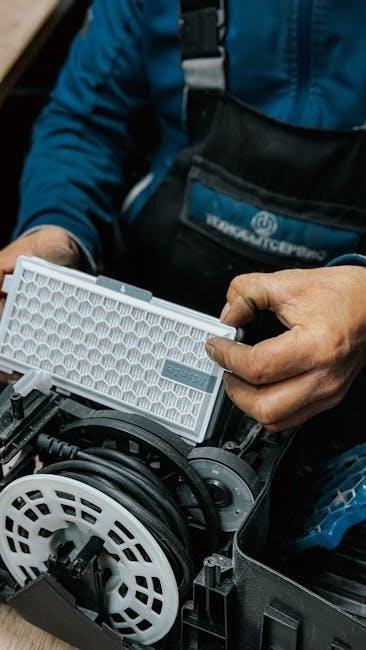
Regularly cleaning the air filters is arguably the most important aspect of Mitsubishi mini-split maintenance. Dirty filters restrict airflow‚ reducing cooling and heating efficiency‚ and potentially damaging the system. The installation manual stresses the importance of this simple task.
The frequency of cleaning depends on usage and air quality‚ but monthly inspection and cleaning are generally recommended. In dusty environments‚ more frequent cleaning may be necessary. Before cleaning‚ always turn off the power to the indoor unit.
To clean‚ gently remove the filters and vacuum them to remove loose dust and debris. For more thorough cleaning‚ wash the filters with mild soap and water‚ ensuring they are completely dry before reinstalling. Avoid using harsh chemicals or abrasive cleaners.
Reinstalling the filters correctly is crucial for proper operation. Ensure they are securely in place. Ignoring air filter maintenance leads to reduced performance‚ increased energy bills‚ and potential compressor failure. Refer to the operating instructions for specific filter removal and cleaning procedures for your model.
Winterization and Long-Term Storage
Proper winterization is essential for Mitsubishi mini-split systems in colder climates to prevent damage during freezing temperatures. The installation manual doesn’t explicitly detail winterization‚ but long-term storage requires careful preparation. Disconnecting power is the first crucial step.
For extended periods of non-use‚ thoroughly clean both the indoor and outdoor units‚ including the air filters. This prevents mold and mildew growth. Consider covering the outdoor unit with a weatherproof cover to protect it from snow‚ ice‚ and debris‚ but ensure adequate ventilation;
It’s recommended to evacuate the refrigerant lines by a qualified technician to prevent moisture buildup and potential corrosion. While not always necessary‚ this step offers significant protection. Ensure all water drain lines are completely clear to prevent freezing and cracking.
Before restarting the system in the spring‚ inspect all components for damage. A professional inspection is advisable to ensure proper operation and refrigerant levels. Following these steps will maximize the lifespan and efficiency of your Mitsubishi mini-split system.